Nikon SB-5000 Speedlight: Advanced Air-Cooling System and Engineering Insights
With a powerful Guide Number of 34.5 m / 113 ft (35 mm) and 55 m / 180 ft (200 mm) (ISO 100, FX format, standard pattern), combined with an extremely wide 24–200 mm zoom range (extendable to 14 mm with the built-in diffuser panel), the SB-5000 delivers professional-grade output and coverage flexibility.
Nikon SB-5000 Speedlight: Advanced Air-Cooling System and Engineering Insights
Important Safety Notice and Warning
This article is written solely for educational observation and research purposes, with the goal of understanding product design principles and engineering excellence.
NEVER attempt to open, disassemble, or service the Nikon SB-5000 (or any flash unit) yourself. It is strongly not recommended for the general public to open or study internal components without expert guidance and proper safety equipment.
High-voltage components inside flash units can retain lethal charge even when unpowered and can cause serious injury or death. Internal structures and components may also feature sharp edges or other hazards.
If you notice any abnormality or require repair, always seek professional service from Nikon authorized centers or qualified technicians.
This article is not a repair guide, teardown tutorial, or service manual — it is strictly for informational and educational viewing only.
The content here is shared for personal educational use and reference by experienced technicians only. It details my hands-on study process and findings for informational purposes. If you're unfamiliar with flash unit structures, lack technical expertise, or do not have proper tools, do not attempt replication. Always consult Nikon authorized service centers or professionals to avoid voiding warranties or risking safety.
Key Technical Specifications
- Guide Number: 34.5 m/113 ft (35 mm), 55 m/180 ft (200 mm) at ISO 100 (FX format, standard pattern).
- Zoom Range: 24-200 mm (FX format); 14 mm with wide panel.
- Illumination Patterns: Standard, Even, Center-weighted; auto-adjusts for FX/DX formats.
- Bounce Capability: Tilts from -7° to 90°; rotates 180° left/right with detents.
- Recycling Time: 1.8 sec (Ni-MH batteries), 2.6 sec (alkaline); minimum 150 flashes per charge.
- Flash Duration: From 1/980 sec at full power to 1/30,820 sec at 1/256.
- Wireless Control: Radio (up to 98 ft/30 m) and optical; supports master + 6 groups (radio) or +3 groups (optical).
- Power Source: Four AA batteries; compatible with SD-9 High-Performance Battery Pack or SK-6A Power Bracket.
- Dimensions & Weight: 73 x 137 x 103.5 mm; 420 g (body only).
- Electronic Construction: Automatic IGBT with series circuitry for efficient power management.
- Additional Features: i-TTL flash control, AF-assist illuminator, modeling light, thermal cut-out, and flash compensation (±3 EV in 1/3 steps).
Internal Analysis of the device
 |
| Nikon SB-5000 |
Battery Chamber and Mounting Foot


Front Shell and Circuitry
A sync terminal (silver) and light sensor for non-TTL auto flash occupy the lower corners.

WARNING: High-voltage hazard! Do NOT attempt to open or service this device. Professional service only.
The black IGBT (Insulated Gate Bipolar Transistor) board rests atop the white lamp shade. A flexible printed circuit (FPC) links the zoom motor and flash tube controls. Notably, multiple thermal sensors are embedded in the flash lamp unit—a rarity in Speedlights, indicating advanced overheating protection.
The FPC includes four sensors and two buttons for detecting accessories like color filters or bounce adapters, allowing adaptive settings when an accessories was mounted to the flash head.

Under the IGBT board, there is a transparent plastic cover over the air supply line, fed by a rear-mounted pump (thin square-shape black color component).

Lamp Shade and Flash Lamp Unit
- A dark gray reflector holder (likely glass-fiber-reinforced PPS thermoplastic, rated for 200°C+ service temperature—superior to standard plastics).
- A stainless steel frame.
- A quartz glass window.
- A high-polish metal reflector.
- A xenon flash tube.


The Heart of Cooling: Piezoelectric Micro-Blower


This image reveals the lamp shade assembly, clearly exposing the precisely engineered J-shaped air channel. This specialized canal directs the pressurized airflow generated by the piezoelectric micro-blower toward the critical heat-generating components of the flash lamp unit.


Detailed close-up of the air nozzle cover.
The integrated air-cooling system employs a piezoelectric micro-blower and three 0.35 mm precision orifices to deliver a directed stream of pressurized air into the critical gap between the flash lamp unit (including reflector and tube) and the protective acrylic Fresnel lens.

During continuous or rapid high-output firing, radiant and conductive heat from the flash tube is absorbed by the Fresnel lens, causing rapid surface temperature elevation. Without active cooling, this would quickly lead to thermal deformation or melting of the acrylic material.
The cooling airflow is specifically channeled to create forced convection across the rear surface of the Fresnel lens, extracting heat and distributing it into the larger internal air volume of the flash head. This mechanism substantially delays the onset of localized overheating and reduces peak temperatures at the lens.
Nevertheless, the instantaneous heat generation of a full-power (GN 55) discharge significantly outstrips the continuous heat removal capacity of the micro-blower (~1.2 L/min). Consequently, when the flash firing frequency exceeds the cooling rate, the Fresnel lens temperature will still rise progressively.
Furthermore, the flash head operates as a deliberately sealed environment to maintain dust protection. This closed system means that prolonged operation causes the internal ambient air temperature to increase steadily, reducing the thermal gradient available for convective cooling and imposing a fundamental limit on sustained high-power performance — regardless of pump output.
Additional Internal Discoveries
WARNING: High-voltage hazard! Do NOT attempt to open or service this device. Professional service only.
Beyond its groundbreaking air-cooling system, the Nikon SB-5000 incorporates a wealth of other sophisticated engineering details that make it a true flagship Speedlight. Here are some additional highlights that enthusiasts and professionals often find particularly impressive.
On the left-hand side of the battery compartment sits a compact light-sensor circuit board. It is specifically designed to receive and process optical pulses for Nikon's Creative Lighting System (CLS) wireless remote flash control.

One of the most striking aspects of the SB-5000's internals is the impressive quantity of circuit boards — they occupy virtually every cubic centimeter of space inside the body.
Yet, despite this complexity, the wiring harnesses, connectors, and board placement are executed with remarkable neatness and clarity. The thoughtful layout ensures that critical connectors and boards remain relatively straightforward to reach and work on when needed.


Mounted beneath the battery chamber are two key components:
- A dedicated radio circuit board (model 1EK), which handles the SB-5000's advanced wireless radio communication (AWL – Advanced Wireless Lighting) for reliable master/slave operation up to approximately 30 meters.
- A compact piezo buzzer element, used for audible alerts and feedback during operation.

Without the battery chamber installed on the rear housing, the main circuit board becomes fully visible. All user controls — including the buttons, rotary selector, and LCD display — are mounted on the opposite (outer) side of this main board, directly accessible from the back panel of the flash.

A large copper heatsink is mounted directly onto the inverter circuit board. This substantial heat radiator plays a critical role in dissipating the significant thermal load generated during high-voltage flash charging and operation.


The main circuit board is densely populated with a wide array of electronic components, reflecting the sophisticated design required to manage the SB-5000's control logic, and user interface functions.

Extreme close-up of the micro-coaxial cable assembly.

Innovative Flash Tube Mechanism
WARNING: High-voltage hazard! Do NOT attempt to open or service this device. Professional service only.
Revolutionary flash tube holder & reflector structure — the most intricate and advanced flash lamp assembly I have encountered in any Speedlight.

The SB-5000 introduces a genuinely novel engineering solution: the Swing Tilt Angle Holder.
This precision mechanism enables the flash tube to shift slightly forward and backward within the parabolic reflector. By dynamically adjusting the tube's position relative to the reflector's focal point, Nikon achieves more consistent and efficient light output — especially noticeable when transitioning between different zoom angles.

This controlled off-axis placement allows the system to produce either parallel (collimated) or convergent light beams, depending on the exact degree of offset. By dynamically adjusting the tube's position relative to the focal point across the zoom range, Nikon achieves more uniform coverage, improved edge-to-edge brightness, and optimized beam control — a level of refinement rarely seen in portable Speedlights.
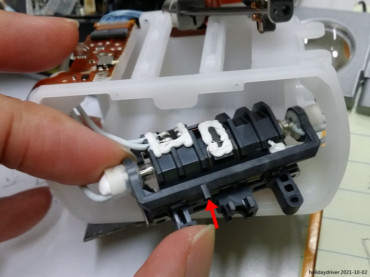
The tilt angle of the Swing Tilt Angle Holder is precisely controlled by a plastic rib (shown below) that slides along a wedge-shaped guide rail integrated into the lamp shade.
This mechanical linkage ensures that the flash tube's tilt angle automatically adjusts in sync with the current zoom setting of the flash head — providing optimal off-axis positioning for each coverage angle.
 |
| Plastic rib |
 |
| Wedge-shaped rail |
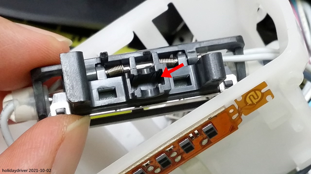
The Flash Lamp Unit is precisely driven by the zoom motor mechanism shown below. A rectangular slot on the Flash Lamp Unit engages perfectly with the high-precision metallic tongue (or spring plate) of the zoom slider.
This tongue (or spring plate) is advanced along a lead screw, which is directly rotated by the miniature zoom motor, enabling accurate and repeatable positioning of the entire lamp assembly across the full 24–200 mm zoom range.
 |
| Miniature Zoom Motor |
 |
| High-precision metallic tongue (or spring plate) |
 |
| A rectangular slot on the Flash Lamp Unit |
The Flash Lamp Unit
WARNING: High-voltage hazard! Do NOT attempt to open or service this device. Professional service only.
The two guide shafts (as shown in the image below) holding the entire Flash Lamp Unit — including the reflector, tube holder, and tube — to be stay in one piece.

|
| The alignment holes of guide rail |

|
| Guide rail diameter measurement |
This assembly is rigidly supported at both ends by the Tilt Angle Holder, which provides secure, vibration-resistant mounting while still allowing the controlled linear movement required for the off-axis zoom adjustment system.
 |
| Flash tube is protected by a soft, milky-white rubber sleeve |
 |
| The grey color wires and side view of the holder |

Given its size, placement, and direct thermal contact, this sensor is almost certainly intended to provide real-time monitoring of either the reflector’s surface temperature or the internal air temperature within the sealed flash head enclosure — both critical parameters for the SB-5000’s advanced thermal protection system.
Additionally, the prominent cooling fins integrated into the reflector holder clearly serve to increase surface area and enhance passive heat dissipation, helping to manage thermal load during extended or high-power operation.

|
| Thermal sensor is mounted to the rear surface of the reflector holder |
The holder is spring-loaded and can swing/pivot freely within its designed range, demonstrating the smooth, low-friction mechanism that enables precise angular adjustment during normal operation.
 |
| The holder can swing freely up |
 |
| The holder can swing freely down |
 |
| Nikon SB-5000 flash tube |
 |
| The cathode of the flash tube |
 |
| The anode of the flash tube |
 |
| Close of the anode |
A secondary sensor is bonded to the back of the metallic reflector, providing direct and accurate temperature feedback from the component that experiences the most intense radiant heat from the flash tube — an excellent example of the SB-5000's comprehensive thermal protection strategy.
 |
| The metallic reflector with sensor on it |
 |
| Front view of the metallic reflector |
 | |
|
Conclusion
家用電子電器保養心得
留言